The Making of the Part
Start with the rectangle and draw circles and connecting lines with all correct dimensions. Then trim away excess lines and extrude. Next start a new sketch with two circles around the upper circles and lines across the bottom to make the correct shape. Then trim the bottoms of the circles and extrude.
|
|
|
|
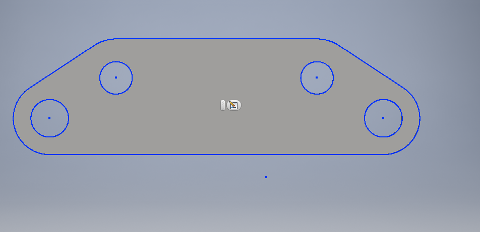
This is what the first sketch should look like before extruding.
|
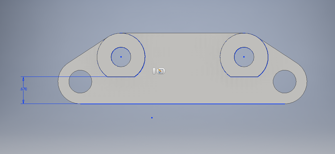
This is the second sketch where you add the circles that will stick out further.
|
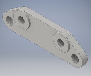
This is what the final brake bracket should look like on Inventor.
|
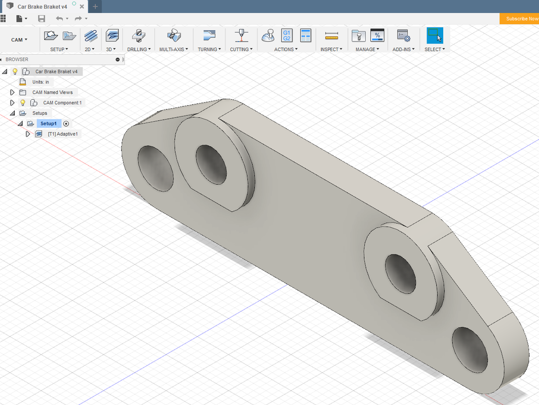
Setting up on Fusion
|
|
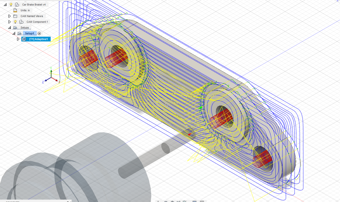
Open the part in fusion 360 and set up the tool paths using the 3D adaptive contour. They should look similar to the picture above. Then save the G-Code onto a USB or the mill computer. The part is now ready to be milled out.
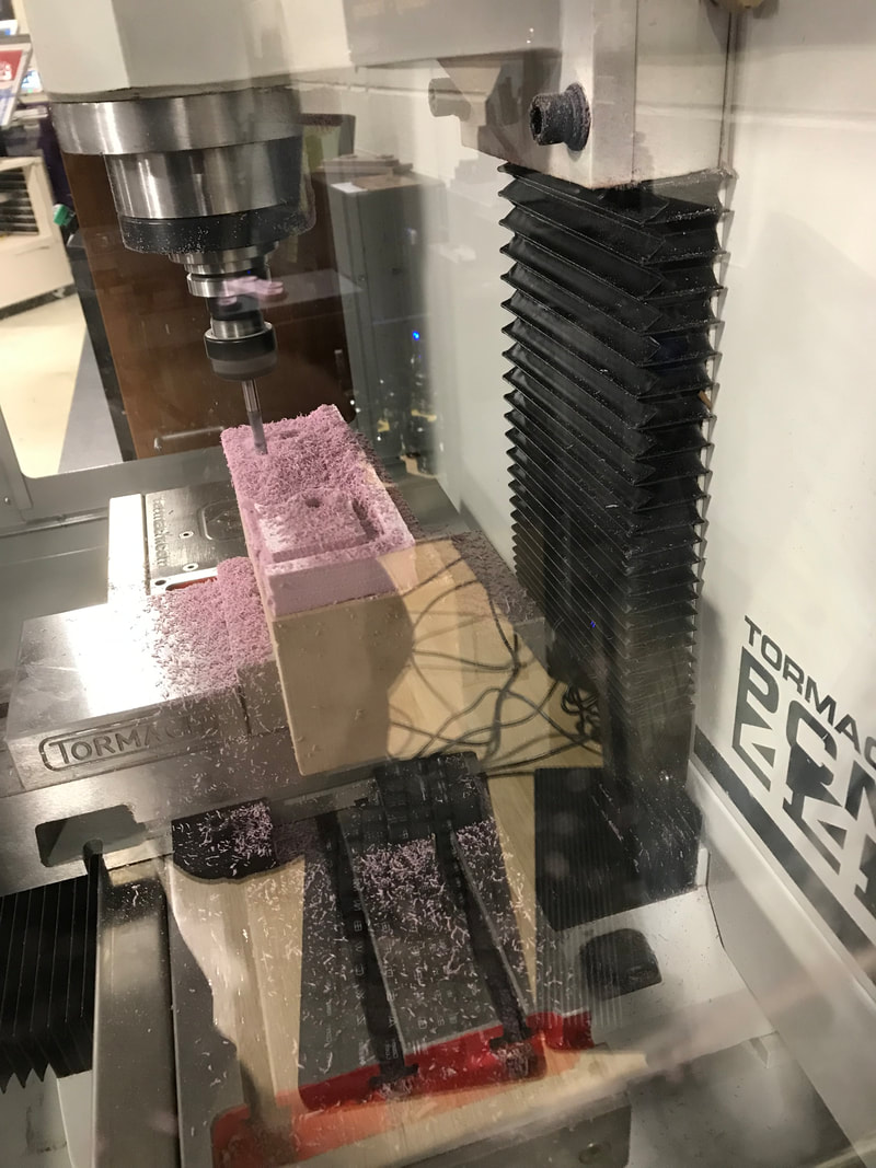
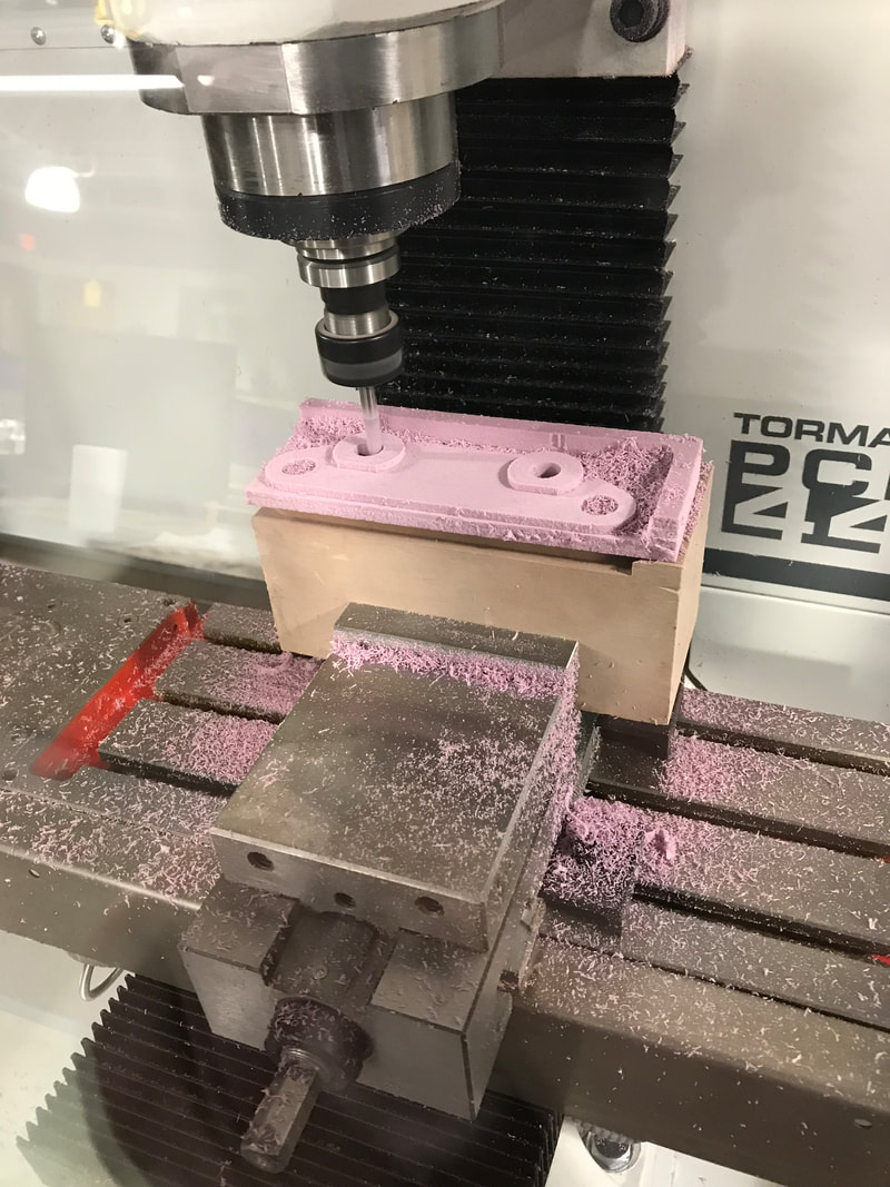
My Part Being Milled
|
|
|
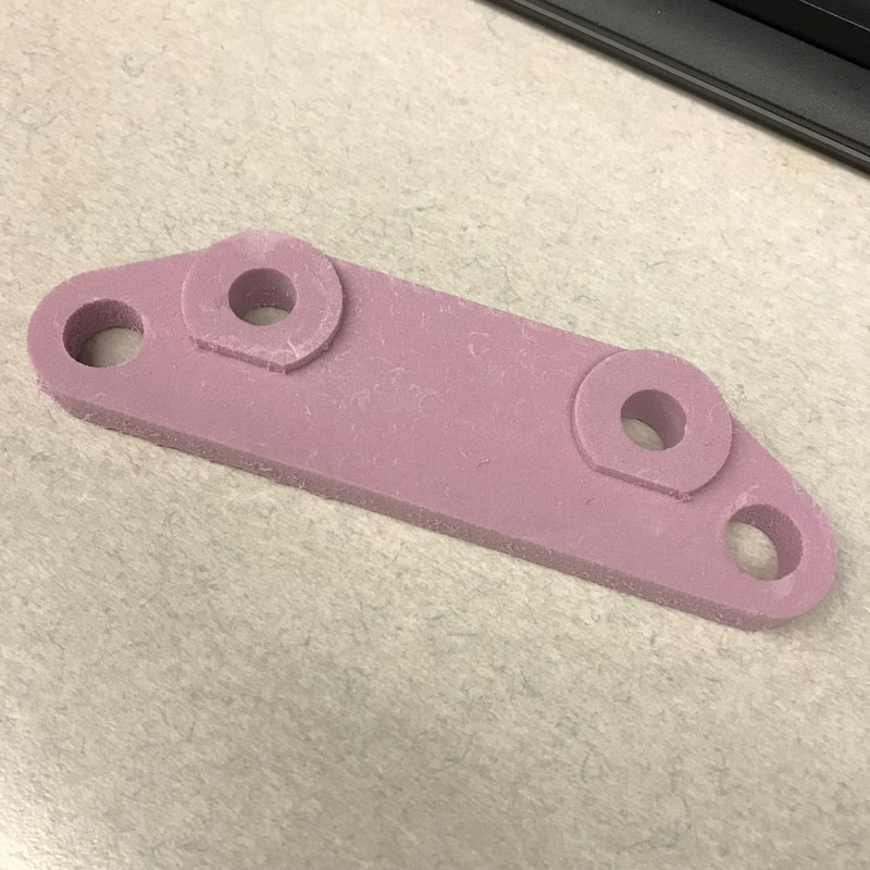
My Final Brake Bracket
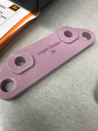
In Summary
The CNC mill is one of the most useful machines in the innovation center. It can create any 3D object in detail as long as it fits in the mill. Like the router it drills away material to create the objects. The mill uses a 3D adaptive clearing path in order to make the brake bracket. Unlike the 2D paths for the maze the 3D paths are automatically generated by Fusion. Throughout this project I have learned how to better use Inventor, Fusion, and the CNC mill. I learned about the tangent tool in Inventor, 3D milling in Fusion, and how to get G-code and enter it into the mill.
