Inventor is an engineering computer software that is designed to aid in designing and building different parts or assemblies. It can be used in a variety of ways from simple 2D drawings to 3D objects to even making complex multi part machines. We used Inventor to sketch, extrude, and create 6 different widget designs and then to 3D print one of the widget designs.
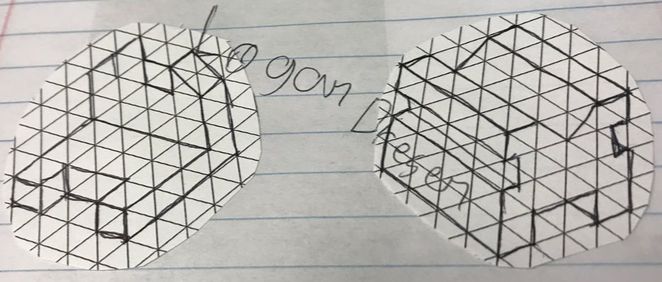
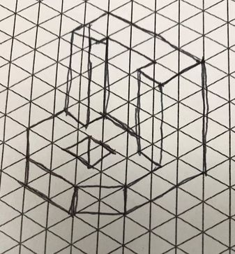
These are some of the sketches we did before moving on to the computer. They are like the blueprints for what we want to make in inventor.
These are the 6 widgets that we created using the Inventor 3D modeling software.
6 steps to making a 3D model on Inventor
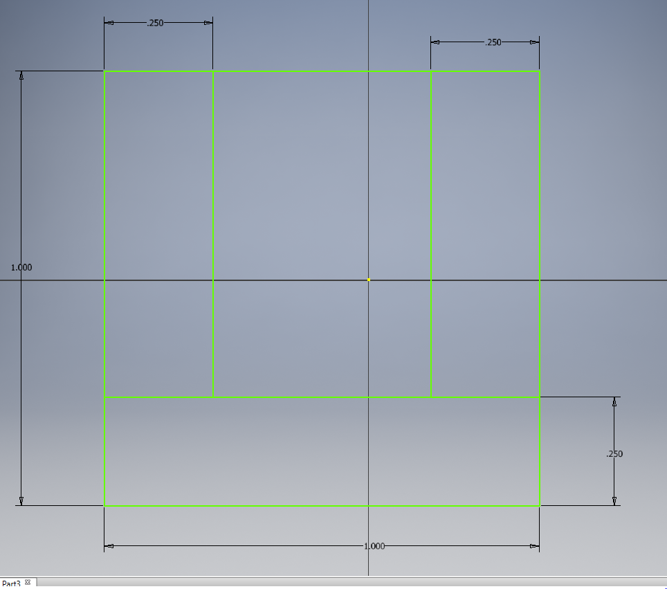
1. Start with a 2D sketch, draw a square and dimension it to be 1 in by 1 in. Finish sketch
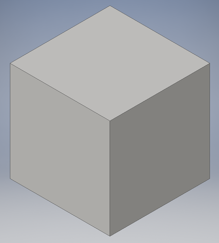
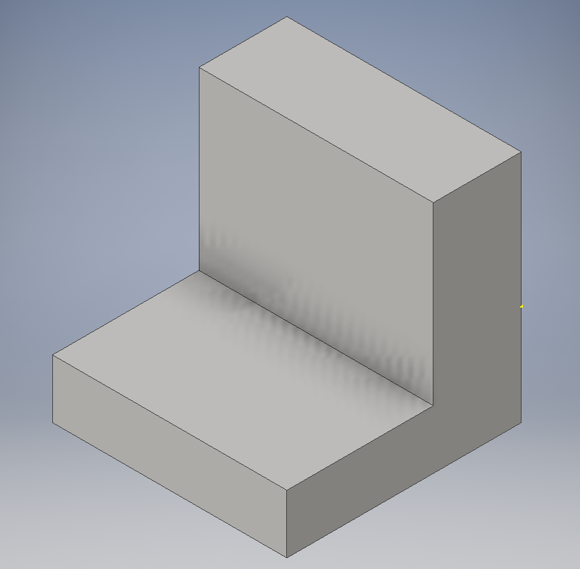
2. Extrude your square by 1 in and make a cube
3. Start a sketch on the right face of your cube, make a rectangle and dimension it to be 5/8th of an inch by 3/4th of an inch. extrude in direction 2 by 1 inch to make the chair-like shape.
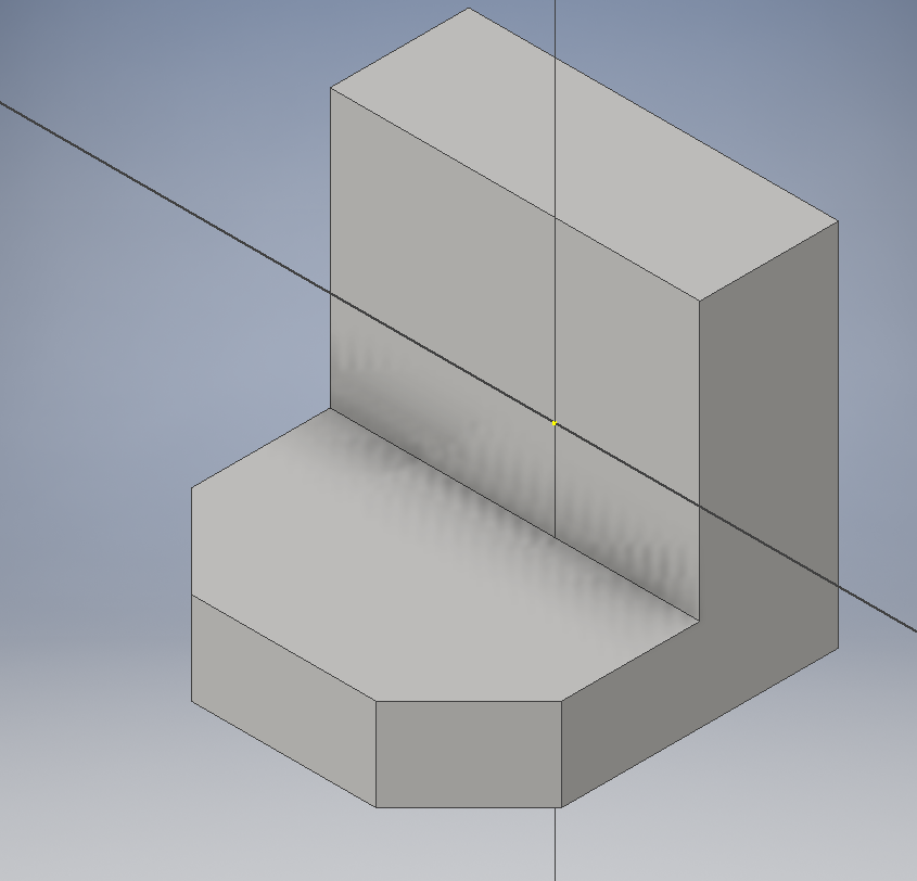
4. Next you have to take the corners off of the bottom section of the shape, to do this use the chamfer tool to get flat edges on the part. To do this select the chamfer tool, click the two corners and set the distance to .25 inches.
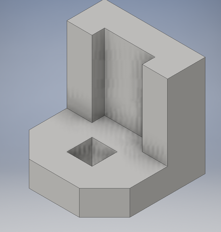
5. Now to get the indent in the top section of the part start a sketch on the top face of the part and draw a 1/8th in by 1/2 in rectangle that is equidistant from either side of the part and aligned with the front of the back section of the part.
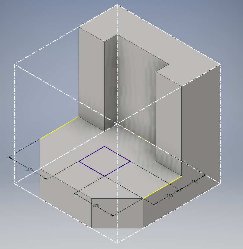
6. Lastly to get the hole in the bottom section of the part start a sketch on the bottom section and sketch a .25 in by .25 in that is .25 in from the front of the part and .375 in from each side. Then finish the sketch and extrude in direction 2 to form the hole.
1. Start with a 2D sketch, draw a square and dimension it to be 1 in by 1 in. Finish sketch
2. Extrude your square by 1 in and make a cube
3. Start a sketch on the right face of your cube, make a rectangle and dimension it to be 5/8th of an inch by 3/4th of an inch. extrude in direction 2 by 1 inch to make the chair-like shape.
4. Next you have to take the corners off of the bottom section of the shape, to do this use the chamfer tool to get flat edges on the part. To do this select the chamfer tool, click the two corners and set the distance to .25 inches.
5. Now to get the indent in the top section of the part start a sketch on the top face of the part and draw a 1/8th in by 1/2 in rectangle that is equidistant from either side of the part and aligned with the front of the back section of the part.
6. Lastly to get the hole in the bottom section of the part start a sketch on the bottom section and sketch a .25 in by .25 in that is .25 in from the front of the part and .375 in from each side. Then finish the sketch and extrude in direction 2 to form the hole.
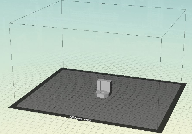
This is an image from the Makerbot software we used to build our 3D objects
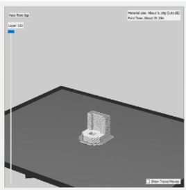
This is the preview of what our finished product will look like after it is printed
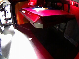
Here is a picture of the widget in the middle of the print
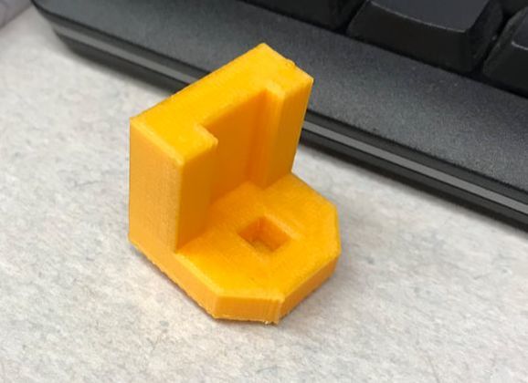
This is the what the widget will look like after it has been 3D printed

After this 3D design project I have become better at using inventor. I learned how to design and create anything from 2D sketches to complex parts on the software and how to 3D print them as well. In addition I learned how to export my Inventor files into Makerbot and now I am able to design and print any 3D shape I can think of. Also I learned many new techniques to make designing on inventor easier. I previously had some experience with Inventor but it was a few years ago so I thought I might be a little rusty. Overall it is a very user-friendly software and it was simple to pick up the basics again and then to remember some of the more difficult methods of creating 3D models.
